안녕하세요.
PLC 읽어보기 작업 후 오랫만에 다시 포스팅 합니다.
Mitsubishi, Omron PLC 읽어보기가 마무리 안됐는데 시간되면 작업해서 포스팅할 예정입니다.
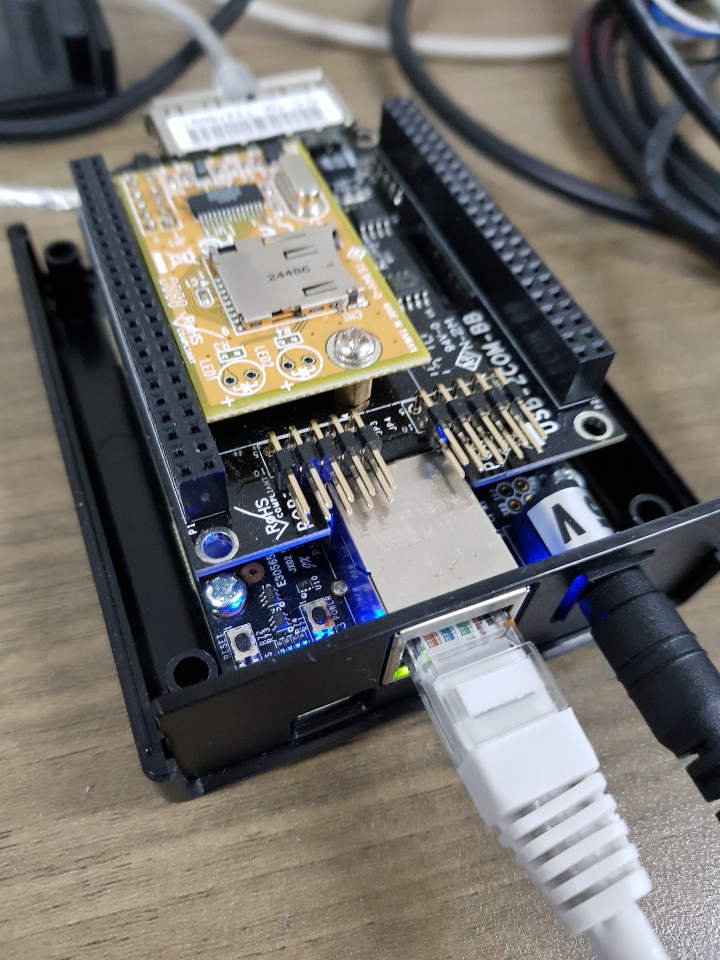
이번에 작업한 내용은 위즈네트 W5500 칩과 ESP32-WROOM 모듈을 이용하여 이더넷 연결을 해 보았습니다.
W5500 칩을 MACRAW 모드로 사용했기에 ESPRESSIF사의 개발플랫폼인 IDF(IoT Development Framework)에 있는 다양한 프로토콜 예제들을 모두 Reuse할 수 있다는 장점이 있으니 한번씩 살펴보시기 바랍니다.

| Spe Specificationcification | |
| Processor | Tensilica dual-core Xtensa® 32-bit LX6 MCU |
| Crystal | 40 MHz |
| ROM | 448 KB |
| RAM | 520 KB |
| QSPI flash/SRAM | 4 MB |
| Ethernet | WIZnet W5500 10/100 Ethernet MACRAW Mode |
| User Input | Boot Button / Reset Button |
| Connectivity | WiFi, BLE |
| IO | GPIO 20 pins connector with all ESP32 ports |
| Protocol | Built-in programmer for ESP-IDF and Arduino |
| Operating Voltage | 3.3V |
| Input Voltage | 2.7~5.5V |
| Dimension(mm)/Weight | TBD |
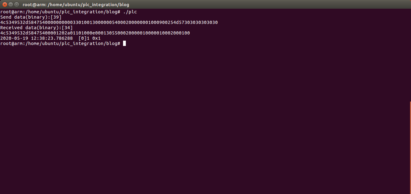
Result :


다음 회부터 IDF 개발환경 셋업, 보드 구성, 소스 작업의 순으로 포스팅할 예정이니 기대해 주시기 바랍니다.
'오픈소스 HW > WIZnet' 카테고리의 다른 글
| WIZnet WizFi630A HOWTO - Upgrade (0) | 2017.06.01 |
|---|---|
| WIZnet WizFi630A HOWTO - Build (0) | 2017.06.01 |
| How to porting WIZInterface library into mbed OS5 temporarily (0) | 2016.12.23 |
| TFTP Example on WIZwiki-W7500 platform (0) | 2015.10.14 |
| Convert ioLibrary into BSD socket style on WIZwki-W7500 platform (0) | 2015.10.06 |


 loopback.tar


 mbed_blinky_WIZWIKI_W7500.bin


